Order Digital Reprints
Filed Under
Sign Me Up!
Sign up Digital!
Subscribe to Print!
Interested in Manholes?
Get Manholes articles, news and videos right in your inbox! Sign up now.
Manholes + Get AlertsWhere there’s a pump, operators need some means of control and monitoring. Digital technology makes it possible to create smaller yet more sophisticated control systems.
MultiTrode, based in Boca Raton, Fla., has developed the MultiSmart Pump Station Manager, an electronic control system for monitoring and controlling individual pump stations. The company also provides PumpView Web-based software for remote control of a utility’s entire system of pump stations.
On Oct. 17, Travis Walker of the Beaver Dam municipal wastewater utility demonstrated the functions of the city’s MultiSmart manager installed on one of the city’s 13 sewer system lift stations. On Sept. 28, Aaron Parkinson of MultiTrode demonstrated PumpView software using a Web-based simulation. On Oct. 28, he conducted a remote demonstration using a real-life PumpView installation at New Bedford, Conn.
Walk-around
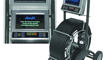
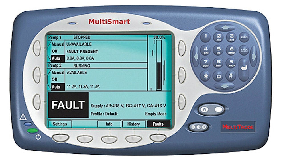
The MultiSmart Pump Station Manager is encased in a blue-and-silver plastic housing about 7 by 8.5 inches and 6 inches deep. A pump system data display screen takes up about two-thirds of the front. A series of control buttons ring the screen, and a 12-button telephone-style numeric keypad at the upper right corner of the casing is used to program information into the device.
The PumpView software is a Web-based application launched in an Internet browser. It uses a graphical interface on which operating personnel can observe and control the functions of a municipality’s pump system.
Operation: MultiSmart
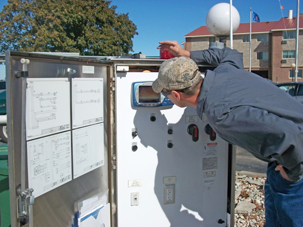
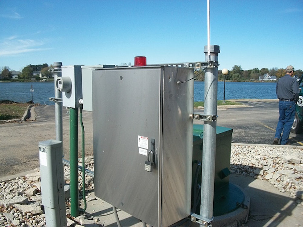
The MultiSmart unit demonstrated in Beaver Dam was located outdoors at a sewer system lift station serving part of the southwest area of the city. Rob Minnema, water and wastewater utility foreman, said it was installed about two years ago during an upgrade of the lift station’s controls. Thus far it is the only MultiSmart unit in service in the city.
For the demonstration, Walker unlocked a metal housing to show the MultiSmart unit inside. He punched a succession of buttons on the unit to display the various information screens with which it was configured.
The first screen indicated the status of the lift station’s two pumps, which were set to AUTO and programmed to operate in alternating sequence. The screen included a label showing which pump was next to run; labels also indicated how long each pump had run last (two minutes in this case). A vertical bar at the left edge of the screen provided a visual indication of the water level in the pump station — about 40 percent at the time of observation.
Additional screens showed a history of the pumps’ operation, listing run-time hours, faults, failures to start, and other events. For example, according to Walker, Beaver Dam periodically checks that the two pumps are properly alternating operation. Additionally, the control monitors the volume (in gallons) that each pump moves at a given time. If one is pumping less and the other more, that may indicate that one pump is clogged or otherwise compromised and in need of maintenance.
“It’s all automatic,” said Walker. “We stop in once a week to check it.” Minnema explained that the device was programmed with the cell phone numbers of several city employees trained to respond to emergencies. In case of an emergency, such as a pump failure, the unit calls the cell phones in sequence until one of the call recipients responds.
Walker noted that the city recently updated the software in its unit, downloading the upgrade from MultiTrode, putting it on a flash drive, then uploading it to the MultiSmart device.
Operation: PumpView
The PumpView demonstration took place in two parts. To show the functionality of various elements of the software package, Parkinson used a simulated version of the application. He then conducted a walk-through via Internet showing an actual installation — the system for New Bedford — without changing the controls so as to avoid disrupting operations at the utility.
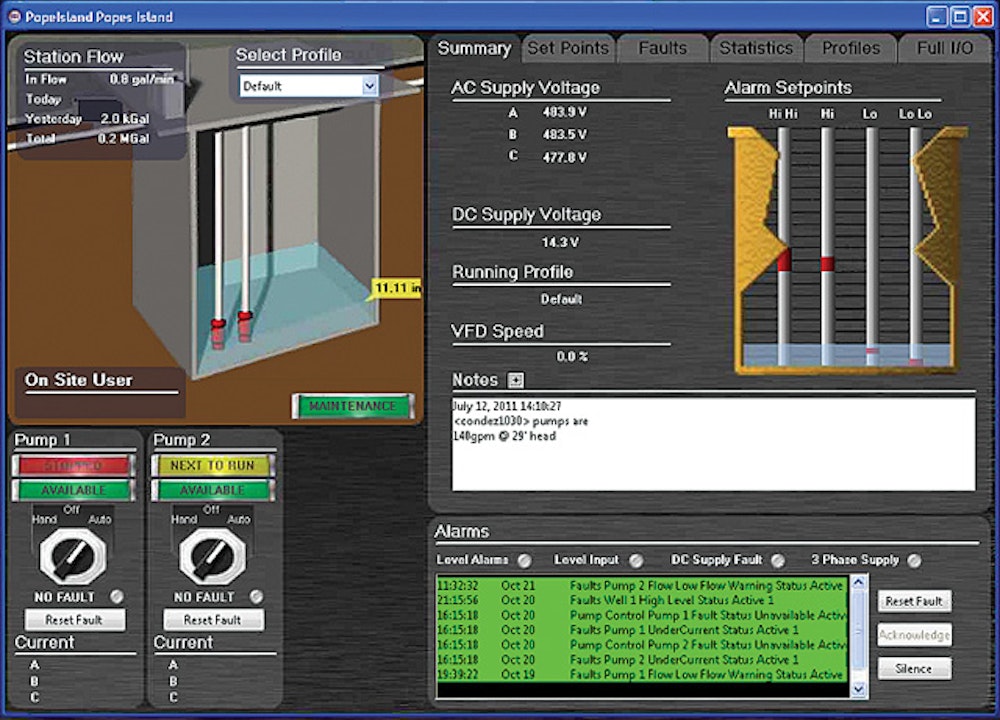
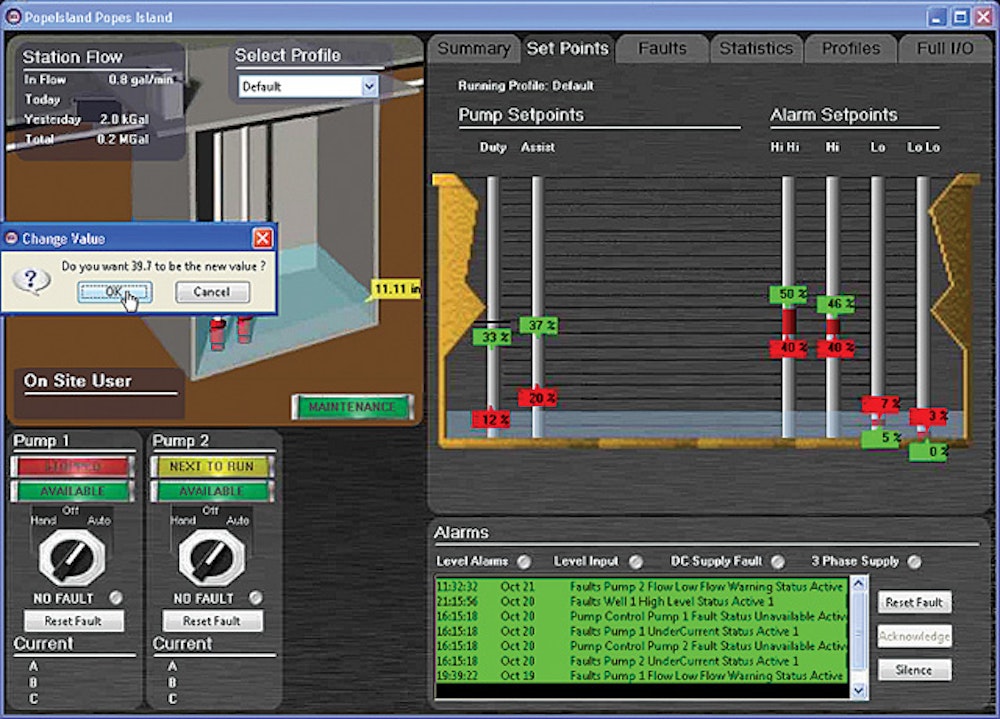
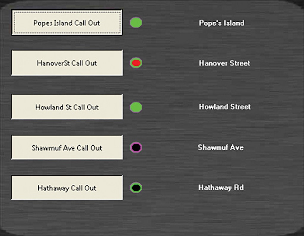
PumpView opens with a screen consisting of a series of buttons, each corresponding to a particular pump station (Figure 1). During the New Bedford portion of the demonstration, Parkinson selected one station, Popes Island. In the window that opened (Figure 2), computer drawings of rotary switches toward the lower left served as the pump controls. They were set to AUTO but could be manipulated using the computer mouse to select other settings: OFF or HAND.
“Over the Web interface, we can start and stop pumps by clicking on that toggle switch and run that pump remotely,” Parkinson said. “If you click the HAND button on one of those pumps, it will send a signal out to the pump station.” When a pump is switched to HAND mode, it runs until it reaches its normal off point, then switches back to AUTO.
Immediately below each rotary switch icon was a bar to reset a fault. Just above the control icons was a representation of the pump station. At the upper left corner of the image was a readout indicating the current inflow rate for the pump station as well as the total volume of inflow for the previous day.
“I’d be able to see how many gallons per minute are coming in,” Parkinson said. “And then for today and yesterday, I’d have the total amount of volume that has been pumped through this pump station.”
To the right of the image was a series of tabs. The first, Summary, presented data on the AC and DC supply voltage to the system, the current running profile (default), and the variable-frequency drive (VFD) speed.
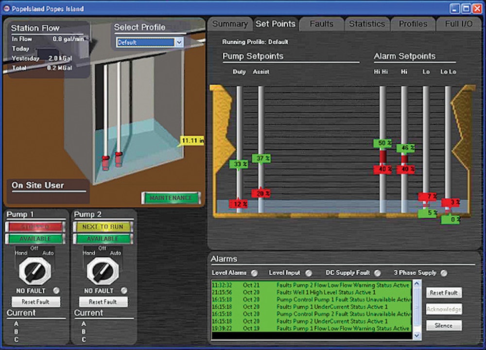
A second tab, labeled Set Points, showed a series of vertical bars with red icons designating the set points for the pumps in the system (Figures 3 and 4). During the simulation, Parkinson showed how to use the mouse to change the set points for each pump.
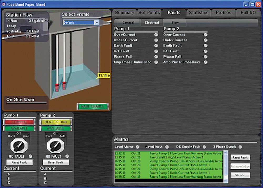
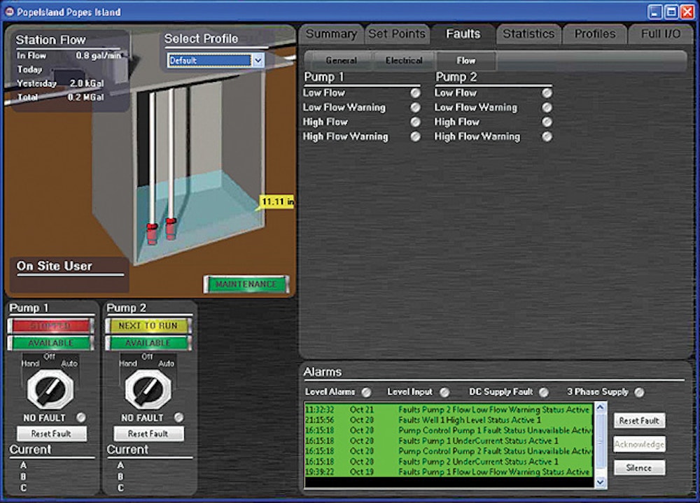
The third tab, labeled Faults, included three subtabs for monitoring general, electrical (Figure 5) and flow (Figure 6) fault conditions. “If you had a problem with a pump, you could zoom in and see what kind of problem you had,” Parkinson said.
Additional tabs allow the operator to view statistics for the system and operation profile options. For instance, a pump station could have one profile for dry weather and another for rainy weather, and the system could be used to reset the profile remotely as appropriate.
Regardless which tabs were open, the operator could see below the tab information a recent fault history for the pump station.
Observer comments
The MultiSmart pump unit was compact and well designed. When installed in an outdoor location, the information screen may be difficult to read on a bright day. Minnema explained that Beaver Dam installed its MultiSmart unit as part of an electrical and control system upgrade for the lift station where it was installed, and that the unit’s design made the job easy.
“We didn’t have to retrofit anything inside the station itself — just bring the wiring into the new MultiTrode panel,” he said. “It’s been very reliable.” He noted the Beaver Dam unit is fairly simple with just the basic functions and data reports; some more sophisticated data options are available with the unit. At one point, the unit’s sensor inside the lift station was regularly building up grease, causing sensor failure. An adjustment to the unit’s sensitivity corrected the problem, Minnema said.
Manufacturer comments
Included in the PumpView system is the capability to generate daily reports in the form of Microsoft Excel spreadsheets. The reports include tabs for hours and run starts, flow, power and efficiency, alarms, data on each pump’s serial number and specifications, and charts comparing the operation of each pump station in the system. Parkinson generated such a report during the simulation demonstration.
PumpView can be set to a maintenance mode, so that when an employee is at the pump station, alarms created by the maintenance work do not call up other users. “It’s not going to create more alarms,” Parkinson explained.