
Order Digital Reprints
Filed Under
Sign Me Up!
Sign up Digital!
Subscribe to Print!
Interested in Cleaning?
Get Cleaning articles, news and videos right in your inbox! Sign up now.
Cleaning + Get AlertsToolboxes might seem to be the simplest of devices in any shop, but a new toolbox system from Snap-on Industrial helps teams of workers keep track of shared tools, identify which ones are due for calibration, and even log when tools are out of service for repairs.
The Level 5 ATC Tool Control System is part of a larger family of products from Snap-on aimed at helping tool users organize, secure and manage their tools and other supplies as assets. The Level 5 ATC consists of a toolbox equipped with a digital scanning system that automatically makes a visual record of the removal and return of tools, along with proprietary software that keeps track of that information.
The system was developed for military, aerospace and utility industry settings, where inadvertently leaving a tool behind, such as in an aircraft jet engine or in a power-generation turbine, can result in damage and pose a safety hazard. But Snap-on officials believe the system has broad applicability to larger workgroups who may share tools and require their effective management as important assets to the operation. The company is looking to interest municipal public works operations in the benefits of the system, officials say.
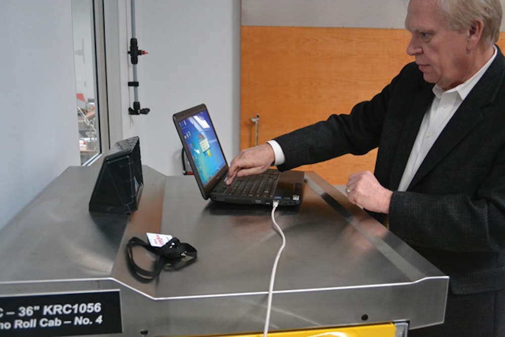
Patrick McDevitt, manager of business development for Snap-on, demonstrated the Level 5 ATC on Jan. 19, 2012, at Snap-on’s world headquarters in Kenosha, Wis.
Walk-around
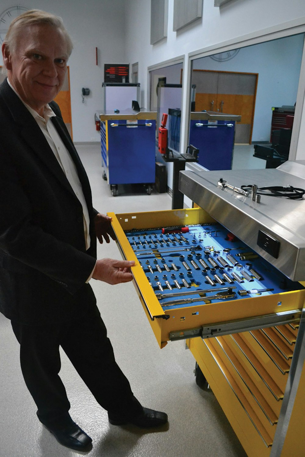
On the outside, the Level 5 ATC is a steel toolbox that stands about chest high when mounted on heavy-duty casters. It’s available in two sizes, one 36 inches wide with a capacity of 450 tools, the other 54 inches wide with a capacity of 750 tools.
Heavy-duty drawers that slide out smoothly are equipped with foam inserts cut to snugly fit the tools stored within. Alternative drawer configurations are available.
An interlocking system prevents more than one drawer from being opened at a time, preventing tip-overs. The top is stainless steel and meets standards as a work surface, while the sides, front and back are available in a choice of colors.
In that respect, the unit resembles conventional Snap-on tool chests. The unit’s security features and asset-tracking features, however, set it apart.
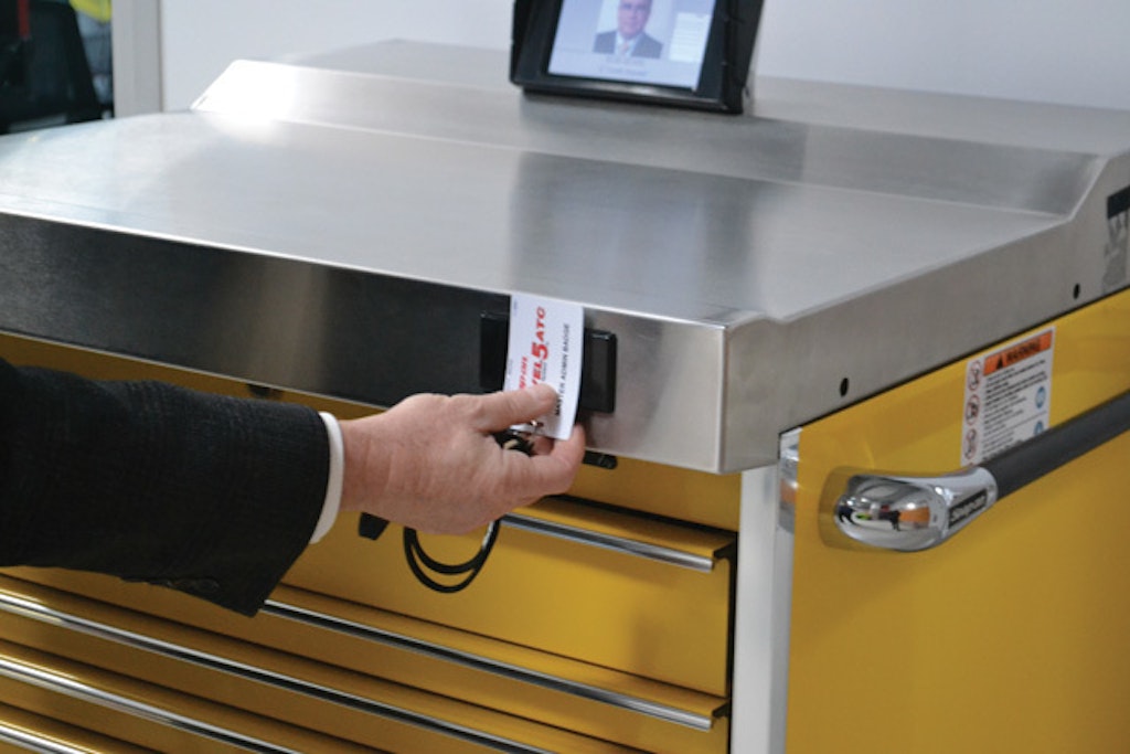
On the top surface is a small touchscreen used to control the system. At the front edge of the steel top is an HID Scanner electronic card reader that unlocks the unit when an approved employee swipes an ID badge over the reader. The touchscreen also records data as it is input by the user who is retrieving or returning tools.
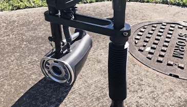
The heart of the system, however, is not normally visible. Inside the unit, level with the top drawer and located at the rear, are four electronic digital cameras arranged in parallel that point straight forward and constitute the scanning system.
At the front of the unit, mounted in the underside of the stainless steel top, is an angled mirror that runs from one side of the tool chest to the other. A lighting system illuminates the contents of each drawer that is opened. In a setup that resembles the optics of a periscope, the contents of the drawer are reflected in the angled mirror. The mirror’s angle, in turn, allows the contents of the drawer below it to be seen by the camera system behind it.
Inside each drawer, running from front to back along either side, there is a pattern of white dots that the software uses to identify which drawer is open and to pinpoint the X-Y coordinates of each tool.
When first set up, an image of each drawer is created with the scanner and filed in a database. Then, as drawers are opened and tools are removed or replaced, the software compares the current state of the toolbox against the baseline images.
“It knows who enters it and it knows what you took,” said McDevitt.
The system can transmit data via either wireless or a cable Ethernet connection to a computer equipped with companion administration software for the system.
Operation
McDevitt began the demonstration by swiping a sample employee badge against the card reader. He pointed out that access can be either granted or restricted to particular cardholders, so that the unit first had to match the cardholder against its database of authorized users of the toolbox.
There was a short electronic beep, and a computerized voice emitted from a tiny speaker in the control unit requested McDevitt to “Select work location.”
The control unit can be programmed with a customized menu listing the specific usual work locations relevant to the toolbox owner, such as by department or perhaps cost center. Logging the intended work location is an optional feature, McDevitt noted, and the purchaser can choose to have it programmed to simply record who is gaining access to the box without identifying a specific work location or application.
McDevitt picked a work department from a short list on the control unit touchscreen. “Access granted,” the electronic voice announced.
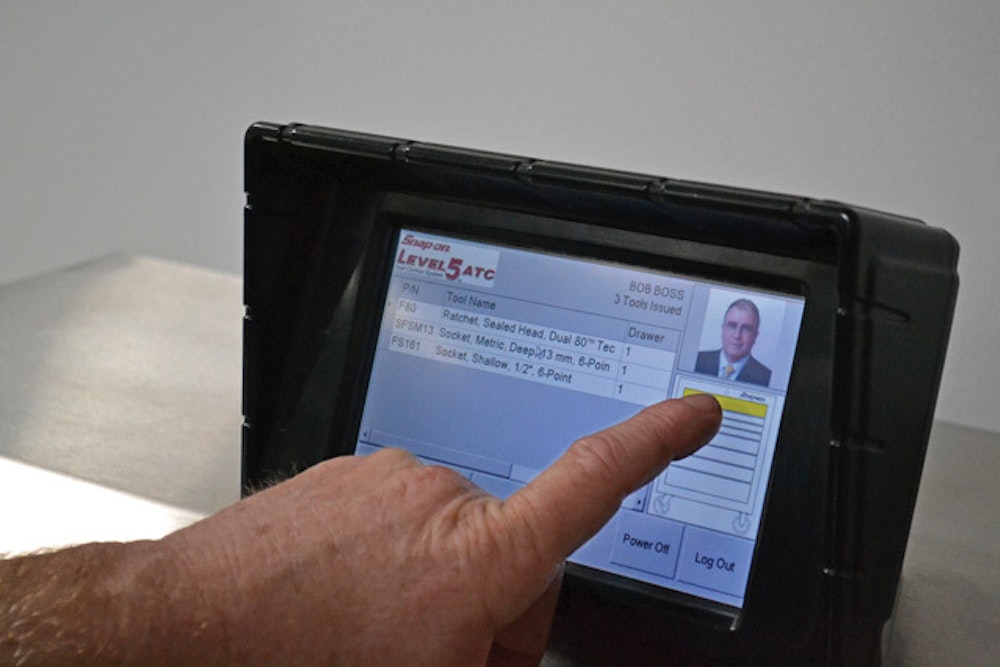
McDevitt opened the top drawer of the toolbox, picked out a ratchet handle and two socket heads, put them on top of the toolbox and closed the drawer. “Issue three,” the electronic voice said — meaning that three items stored in the toolbox had been removed.
The control screen displayed three lines of text, each one showing a part number, the name of the tool removed, and the drawer from which it was taken (each of the three came from drawer no. 1).
To the right of the data was an ID-badge-style photo image of the user. In this instance, it was a fictional user created for the purposes of demonstrating the unit; normally, it would be the photo of the authorized user accessing the toolbox.
Five button icons across the bottom of the control screen allow access to various information screens: “Tools Out,” “Tool Search,” and “Setup” to the left, and “Power Off” and “Log Out” to the right.
He shut the drawer again and touched the “Log Out” button on the control screen. “Log out,” the electronic voice said.
With the tools out of the toolbox, the screen continued to display the list of missing items with each tool’s name, part number, and the drawer to which it is assigned. To the right of the screen, the ID-badge photo of the user was replaced by a padlock icon. A small outline image of the toolbox on the screen was clear, except for the top drawer, which was colored yellow.
McDevitt explained that the colored drawer image was an immediate signal that tools were out of the drawer. “If it were red or candy-cane, it would say there’s an issue in that drawer — maybe a wrong tool, et cetera,” he said.
With the unit once again locked, he used the badge to unlock it. “Select work location,” the voice prompted. McDevitt made a selection and again the unit announced, “Access granted.”
Now McDevitt returned the tools he had removed, putting two in their original storage spots, but deliberately putting the third — a socket — in the wrong spot. He also removed three other tools before shutting the drawer.
“Incorrect tool in drawer one,” the electronic voice said.
It continued: “Return three. Issue three” — in other words, three tools had been returned and three more removed.
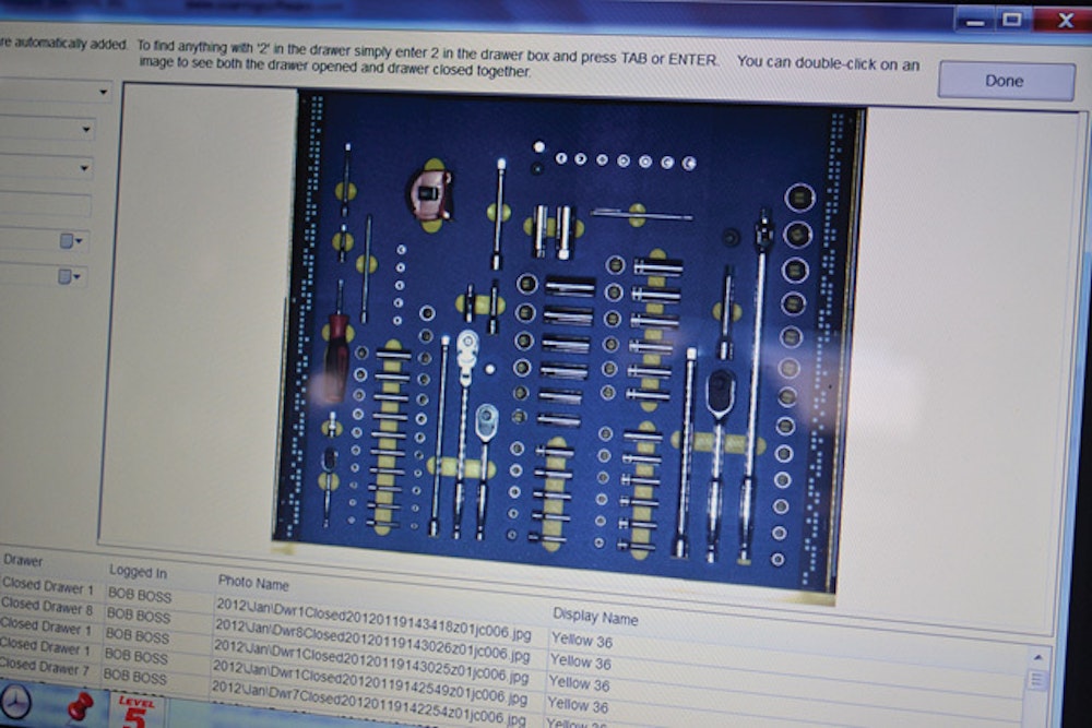
The control screen displayed a digital photo, taken by the scanning system, of the drawer as it was supposed to look when stocked properly.
“This is cuing them to go look there and go fix it,” he said, referring to the deliberately misplaced tool.
The images are also transmitted to the external computer database as part of an audit trail that the machine keeps to enable review of the use of the toolbox and its contents. The audit trail images are time-dated so that if any questionable actions occurred with the unit they would be traceable to the person responsible.
“For example, I could catch a guy who broke a tool and returned it,” McDevitt said. “I can go back through the picture audit trail and see it in good condition and then see it returned as bad.”
McDevitt then removed a total of five tools from three different drawers. The display screen listed them all, showing which drawer each one had been removed from. He explained that a toolbox user who wanted to know who was using a particular “checked-out” tool could learn that by simply touching the icon of the tool on the screen.
“I could find the part number, hit it” — the line on the screen corresponding to the tool — “and say, ‘Ha! Tom took it.’ Then I could go track down Tom.”
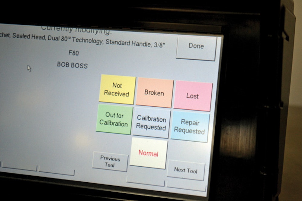
McDevitt then pulled out a ratchet from the drawer. “We’ll pretend this is broken,” he said.
On the touchscreen, he selected the data line for the tool. A new screen appeared with a series of button icons relating to the status of the tool. The buttons were in different colors labeled “Not Received,” “Broken,” “Lost,” “Out for Calibration,” “Calibration Requested,” and “Repair Requested.” He touched the orange “Broken” button. The database was updated to show the tool as broken, and when the screen returned to the list of tools that were out, the line corresponding to the “broken” tool was colored orange.
Alternatively, he explained, for a tool in need of calibration, the “Calibration Requested” button could be pushed.
In addition, for industries where tool calibration is critical, the system can be programmed with the calibration dates for each tool. When the date approaches, it can signal to the user the looming deadline.
McDevitt returned the tool that had been labeled “Broken” to its drawer. The computer voice responded: “Attention! Return one.” McDevitt explained that because he had not cleared the tool as “repaired,” the unit was calling his attention to the fact that a broken tool had been put back in the system. Now he retrieved the tool, touched the data line to bring up the tool status buttons, and touched “Normal.” He then returned the tool to the drawer.
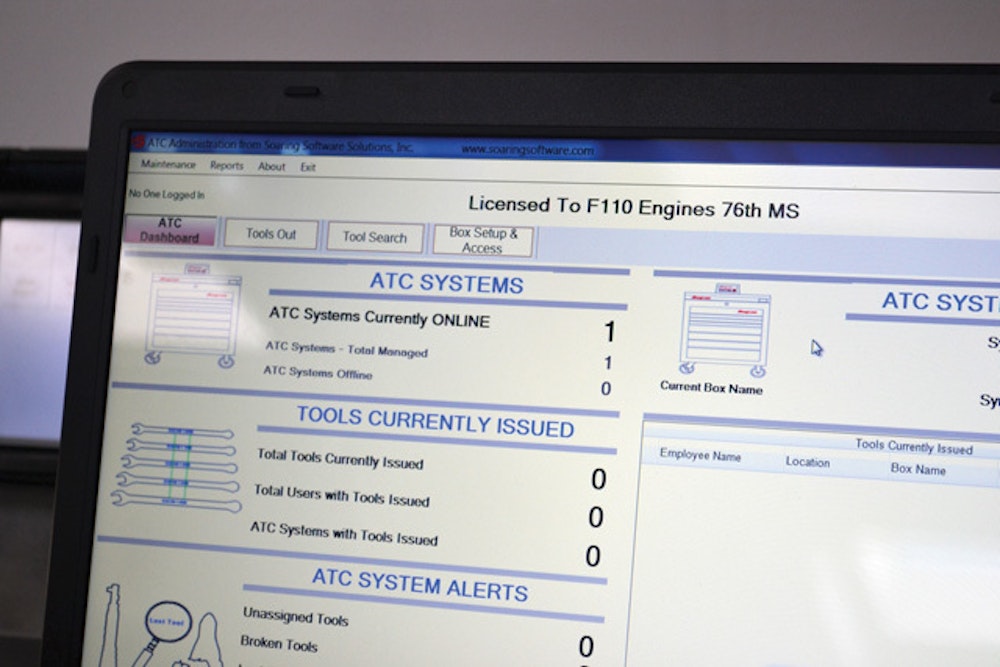
McDevitt then moved to a laptop computer with the system’s administrative software installed. That database is capable of showing the status of the contents of not just the one toolbox but a whole collection of them in a single organization.
The database is searchable by a number of parameters, and synchronizes with the data in the toolbox control unit. It also can be used to track inspection schedules, deadlines and a range of other functions.
Observer’s comments
The system appears swift and accurate to use, and despite the sophisticated information system behind it, retrieving and returning tools does not appear to take any more time or be any more cumbersome than using a conventional toolbox.
Although municipal public works operations may not have some of the same requirements as the industries for which the system was initially created, teams with larger staffs and expensive equipment that requires certification may find it useful as a way of ensuring that a number of expensive assets are kept secure.
Manufacturer’s comments
The greatest use for the system is for expensive tools that require certified users and periodic certification and calibration, said McDevitt. It also reduces the need for tool crib attendants in operations that involve a lot of shared use of tools, or in situations like overnight shifts when it might not be cost-effective to hire a tool crib attendant for an entire tool collection.
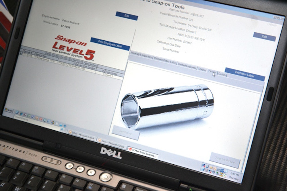
McDevitt said the system is customarily sold along with an entire tool collection, although it is possible for buyers to obtain one for their existing tool sets. The foam inserts can be customized to most tool systems the buyers have, so long as they provide Snap-on with comprehensive information about their size and shape. The company has an extensive library of tool silhouettes it uses to further help in customizing the toolbox. Additionally, the names and part numbers of each tool to be stored in the unit must be entered into the database; that is done using the administrative software package.
While the demonstration model was configured with a “setup” button on the main screen, most standard users wouldn’t have that button, McDevitt said. The button is used to create the initial image database for the toolbox contents.
“We call it training the drawer,” he said. “All you have to do to train this drawer is put the tools in it.”
In the process of setting up the drawer — typically done by Snap-on personnel for the customer’s desired set of tools — images are made of tools in various positions in their designated spot, so that the system can tell a tool has been returned even if it hasn’t been put back in precisely the same way, he said.
Snap-on provides on-site training to all customers upon delivery of the system.
As currently designed, the unit requires an electrical outlet and thus can’t be easily moved around without unplugging and replugging it. A portable, battery-powered version is expected to be released soon, McDevitt said.