Lateral reinstatement is a critical part of cured-in-place pipe lining. The faster new lateral openings can be cut into the newly installed liner, the sooner the sewer can be put back into service, and the less homeowners and businesses are disrupted.
The Dominator 430 cutter, manufactured by Bowman Tool Co. & Systems, is a recent innovation in reinstatement technology. This sled-mounted unit, operated pneumatically and electrically, cuts through the liner at lateral openings and dresses the restored connection for sealing with a grout material.
The machine’s weight, a mere eight moving parts, and an extra-wide sled rail combine to dampen vibration from the cutting process. This virtually eliminates tool chatter and flip-overs. Each attribute is designed to reduce downtime and increase profitability.
Employees of Mr. Rehab Inc., a pipe-lining company based in Mechanicsburg, Pa., demonstrated the device in early April in an 8-inch sewer line in East Pennsboro Township, near the state capital of Harrisburg.
The demonstration began after the original vitrified clay pipe had been lined and the curing process was complete. Crew leader Brian Seeger, assistant cutter operator Wesley Logan, and crew member Kyle McCarthy put the cutter to work. Bowman Tool founder Tom Bowman and daughter Jessica Bowman represented their company.
Walk-around
The Dominator cutter resembles a hydraulic cylinder on sled rails. The cylinder’s central shaft moves in and out of the larger cylindrical body. The shaft can telescope up to 7.5 inches and can rotate 360 degrees. The cutting bit is secured in the air motor’s chuck, which is attached to a sliding shoe. That shoe, in turn, is attached to the shaft.
The bit is about two inches long, has a cross-hatched tooth pattern, and is of a non-fluted design. The large number of teeth delivers a smoother cutting action, which means less wear and tear on all of the motors.
Bowman specified the geometry of the valleys between the cross-hatched teeth to prevent gaulding that occurs when, on occasion, a bit encounters partially cured liner material. Gaulding is the clogging of the flutes on a bit or of the interstitial area between teeth. When a bit gaulds, it must be changed out, resulting in lost production time. Gaulded bits are generally discarded.
The bit and shoe are mounted perpendicular to the telescoping shaft’s centerline and to the surface of the pipe through which the cutter will be pulled. To bring the bit into contact with the work, the shoe and cutting tool slide outward toward the newly installed liner.
By changing the length of the standoffs (or legs) that connect the sled rails to the body, the cylinder is positioned close to the mainline’s center axis. To accommodate pipes of different diameters, either of two interchangeable shoes is used. Pairing the standoff’s length and shoe size enables the cutter to work in 6- to 30-inch lined pipes.
When the cutting bit is replaced with a 3-inch-diameter stainless steel wire brush, the cutter is configured to dress the rough edges of the newly cut hole before the joint is grouted to seal the new lateral connection.
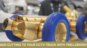
The cutter is deployed as part of a train, which is pulled through the lined pipe by a remotely controlled cable and winch system positioned at the next upstream manhole. The lead component in the train is a sled equipped with a CCTV camera.
The camera’s real-time images allow the operator to monitor and refine positioning, cutting and dressing operations. All the cutter’s actions are controlled at the operator’s station in a CCTV inspection van. Using a dedicated, ergonomic joystick, the operator has infinite control of the tools and can make fine adjustments in position, angle of attack, and depth of penetration.
The Dominator 430 requires 24 V DC current to drive the three DC motors and all control systems. At least 38 cfm of compressed air at 100 psi is required to power the air motor. The electrical components are contained in a watertight chamber, eliminating water damage. The motor chamber is also isolated from the feed and rotation mechanism for ease of assembly and disassembly. Complete teardown and reassembly can be completed in less than 30 minutes in the field. The Generation II Infinite Control single joystick system operates all the air motors.
The cutter has only eight internal moving parts and has no clutches, keyways or set screws. All gears and feed mechanisms are manufactured from temper-hardened stainless steel and bronze. The cutter is machined from a solid billet of stainless steel and has an insulated internal air channel instead of an outside air tube. The head uses a pinionless, quick-change design, and only one adjust-able gib to reduce adjustment time and maintain high accuracy.
The cutter is 33 inches long with the ram in and 40.5 inches long with the ram out. It weighs 72 pounds, and has a body diameter of 3.5 inches. It has a ram travel of 4 to 6.5 inches.
Operation
The demonstration began as the crew deployed a CCTV tractor into a freshly lined and cured mainline sewer. Operator Brian Seeger conducted a visual inspection, identifying each lateral connection and checking the locations with measurements recorded before lining.
When the crawler reached the next manhole, a worker implementing confined-space entry protocols entered to attach a wire rope cable. The crew then reversed the crawler to pull the free-wheeling cable of a remote power winch back to the first manhole. Then they retrieved the crawler with the cable still attached.
While the inspection was underway, working on the floor of the CCTV truck’s equipment bay, Logan prepared the Dominator 430 cutter. He installed the shoe that corresponded to an 8-inch pipe, then installed the cutting bit in the air motor’s chuck. He did not need to change the sled standoffs. He verified that the air-supply hose to the air-powered cutting motor was installed and properly connected.
Logan then placed the cutter on the ground behind a sled-mounted CCTV camera. Using a pair of 18-inch wire rope coupling cables with quick-connectors, Logan and McCarthy joined the camera sled and cutter to form the equipment train. They connected a chain V-yoke to the rails at the front of the CCTV sled, then connected the remote power winch’s wire rope cable. Finally, Logan attached a wire rope yoke, connected to a chain, at the back of cutter’s sled rails.
A custom-spliced, Y-shaped electrical control cable connected the CCTV camera and cutter to the Red Maxx control cable that would stretch back to the CCTV vehicle. To prevent strain on the Y-cable connectors, this cable was secured to the standoffs of the camera and cutter.
In this configuration, the entire train is connected at the front by a wire rope cable and at the back by the control cable, both strong enough to retrieve the entire train. The final assembly step was to quick-connect the air supply to a fitting on the rear of the cutter.
Before inserting the train into the manhole, as Seeger activated each of the machine’s movements, Logan checked for proper operation. He then cleaned the camera lens and LED lights. Seeger, sitting at the inspection truck console, controlled three systems.
The remotely controlled distant winch and the truck-mounted winch system pulled the train forward and backward to position the cutter or camera for optimum efficiency. The second control system operated the CCTV array. The third controlled the cutter. Without getting up, Seeger easily moved from camera to winch to cutter controls, as needed, to advance the work.
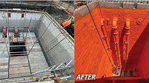
As the train approached the first lateral, the CCTV display showed an irregular circular ridge in the liner. This was the cast iron lateral’s jagged end protruding into the mainline. Seeger made a plunge cut into the liner where it covered the lateral connection. After piercing the liner, he moved the bit toward the lateral’s outer perimeter by moving the shoe as it advanced and retracting the bit.
As he saw and heard the bit engaging the cast iron pipe’s inner wall, Seeger manipulated the cutter so that the bit followed the curvature of the lateral. The process continued until the obstructing piece of liner material fell away in pieces. The 0.8-hp air motor’s exhaust blew the saw debris out of the way and assured a clear view of the work area.
To inspect the work, Seeger engaged the retrieval cable and withdrew the train until the camera enabled him to look into the lateral interior and inspect the newly opened connection. If further cutting is necessary, the distant cable winch can be engaged and the cutter repositioned to finish the job. When the lateral-to-mainline hole is completely cut, the crew pulls the train forward to the next lateral and repeats the process as needed.
After the holes were cleared, Seeger pulled the train forward to the distant manhole. There, Logan removed the cutting bit and installed the wire brush. The train then returned through the lined pipe to the last lateral that had been cut. With the cutter positioned as before, the wire brush, rotating at 30,000 rpm, dressed the connections. The dressing process eliminates burrs and rough spots on the lateral and on the liner’s freshly cut edges. When complete, the dressed cast iron pipe gleamed and the liner was uniformly smooth.
Observer comments
The Dominator cutter performs two tasks and does them well. It is a specialized tool that is part of a team of tools, all essential for successful CIPP lining. Using two winches assures that neither machine can become stranded should one winch or one cable fail.
The inward/outward motion of the cylinder’s shaft, and its ability to rotate and to move into the work afforded the operator optimum tool positioning flexibility. All of these motions were controlled by Bowman Tool’s Generation II joystick and its infinite control capability.
Manufacturer comments
Minimizing the number of moving parts reduces the “play” between those parts, Tom Bowman observes. This eliminates most vibration and wear. Isolation of the motors from the feed and rotation mechanisms in a watertight housing preserves the dry operating environment. It also eases disassembly and reassembly. The unit can be disassembled and reassembled in about 30 minutes, in part because there are no clutches, keyways or set screws.
These machines can be assembled for four-, five- or six-wire control systems, allowing compatibility with other manufacturers’ equipment. “Training at our manufacturing facility is included in the price of the tool,” Bowman says. “If the customer has a complete turnover of personnel, the new employees can come in and be trained without charge as well.
“We have constructed a machine that requires minimal maintenance, and when maintenance is required, it can be performed by the customer in the field.”