Inflow and infiltration in the wastewater collections system draws a utility’s attention. It’s an ongoing threat for sanitary sewer overflows and has a substantial cost once it is received at the wastewater plant. As one senior plant operator puts it, “I don’t like paying to process rainwater.”
By far the most accepted technique to locate and quantify I&I is the flow study. The preferred tools for these studies are area-velocity monitors. To acquire data, these monitors measure water depth in a pipe and its velocity to derive flow. While monitor manufacturers employ a range of specific technologies, A/V monitors generally share capabilities to measure flows with one or more sensors, communicate data from the remote location, capture and/or store data, and provide an output for user viewing and assessment.
The cost of monitors, including installation, can be expensive for utilities with limited budgets and technical resources. Yet these utilities are sometimes under pressure through regulatory agencies or have cost pressures due to excessive flows. As a result, some utilities look toward less-expensive means for assessing I&I sources and have embraced the use of level-only monitors. These monitors measure depth only and use software-driven formulas to calculate flow.
At a fraction of the cost of A/V monitors, they promise a quick and easy way to evaluate I&I entering the collections system. Under ideal conditions, they may be capable of providing flow data, but sanitary sewers don’t always present ideal conditions. To better understand this, it’s important to look at flow basics and review the variables that influence the ability to provide “quick and easy” I&I evaluations.
Flow basics
It is essential to understand collections system flow in order to determine capacity and the effects of I&I for operational performance and asset planning.
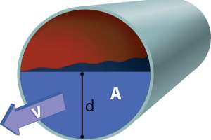
The well-known flow formula is Q = VA, where Q is flow, V is velocity and A is the cross-sectional area of the pipe (see Diagram 1). Flow is derived and typically measured using A/V monitors. Now well established, they provide accurate, repeatable measurements.
Those engaged in collections system flow measurement rely on A/V or flow monitors to conduct their work. Even small collections systems can have thousands of pipe segments and manholes. It would be more favorable to have numerous flow monitors distributed throughout the collections system, but it may be cost prohibitive. Thus, concurrent measurement of many sites can be limited by budget.
Another way
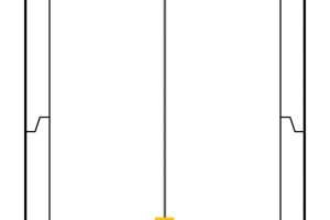
Over the past few years level-only monitors have offered the promise of providing collections system flow data but at a fraction of the cost of A/V monitors. These monitors measure the distance from the sensor to the water below and then calculate water level in the pipe for a given pipe diameter (see Diagram 2).
Level-only monitors do not measure velocity. So, if we are to solve the simple flow equation of Q = VA, we have to account for velocity.
Using Manning’s equation below, it is theoretically possible to determine velocity (v) as shown:
Where factor n is the Manning coefficient (boundary resistance), R is hydraulic radius (of the pipe) and S is slope (of the grade).
We must therefore know these three factors above to successfully arrive at velocity. To do this, we must determine:
Once these factors are accounted for, software is typically used to derive flow (Q). Provided that level-only monitors and software can be used to derive flow, there are some advantages to be realized, as outlined below:
Cost. Level-only monitors typically cost 35% to 60% less than A/V monitors. Thus, users can either measure I&I for less cost or, alternately, deploy more monitors for the same expense. The latter case increases the number of monitoring locations.
Installation. Generally, level-only monitors are easier and faster to install and uninstall. Consequently, they can be more easily moved to a new location if desired.
Level-only advantages seem compelling and even seductive at first glance, but there are other factors at play.
Messy equation
As expected, there are some significant challenges with using level-only monitors for calculating flow. The essential goal is to acquire good-quality measurement data that is accurate and repeatable. Without this, poor-quality, spurious data will lead to erroneous conclusions about flow, I&I sources or system capacity.
As stated previously, level-only monitors do not measure velocity but instead derive it as shown above.
Looking at the velocity formula, S, R and n are the values that must be determined to complete the equation. These values must be accurate otherwise the calculation will be inaccurate. To test potential accuracy, let’s take a look at each value.
- Slope. Often, slope can be obtained from the design drawings. We must then assume that the intended slope noted in the drawing perfectly matches the actual as-built slope.
Experience clearly shows this is a poor assumption, as construction practices do not replicate design to high degrees of accuracy. In addition, segment-to-segment slopes (including the segment leading into the manhole) can be an order of magnitude different from the manhole-to-manhole average slope. Furthermore, the slope in the manhole itself is rarely the same as the assumed slope of piping.
Post-construction, we must also assume that nothing has influenced or changed the pipe slope. For example, we must assume that there is no settling or upheaval. In practice, this is another poor assumption. Therefore, from design to construction and from construction to the current state of the pipe, we see two instances of potential error in calculating slope off drawings. At best, the slope value will be an estimate, and even that can be an order of magnitude off.
- Hydraulic radius. When acquiring a radius of a pipe, several assumptions are made:
Invert geometry and uniformity are not well controlled in construction. All it takes is a random inspection of a dozen or so manholes to show that invert dimensions are not well controlled, nor do they have to be in order to be functional. Therefore, the poor control of geometry and dimensionality are sources of error.
Of special note, any manhole invert with a junction by design has differential radii and cannot be measured with level only.
- Manning’s coefficient. Manning’s coefficient of roughness can be thought of as the resistance to flow on the pipe surfaces. The roughness coefficient can be referenced using published tables based on pipe material. These tables provide the n value in the velocity equation. For example, a concrete pipe is listed as n = 0.015, a vitrified clay pipe is listed as n = 0.013, etc. While useful as a starting point, these values cannot account for actual pipe condition. The roughness tables provide a value range to account for this, but the reality is that judging pipe roughness coefficient is difficult at best. Therefore, the n value is an estimate. Potential error is again introduced.
- Uniform flow. Manning’s equation always assumes there is “smooth, uniform flow.” That’s rarely true in a sewer. Considering such conditions as backwater, drawdown, wavy/choppy flow or transitional slope-change, the equation will be wrong. Transitional flows from such conditions, directional change, obstructions, pipe curves and offsets will violate the Manning’s uniform flow assumptions. Backwater may be the most egregious issue where level is rising but actual flow is not changing.
- Sediment and wetted area. The final step in computing flow is to multiply estimated velocity (v) by wetted area (A) of flow. If sediment is present, this will render the assumed area erroneous. In some cases, this can add massive error to the computation. It is often difficult or impossible to determine the presence of sediment from a topside view only. Even if an attempt is made to account for sediment in the flow cross sections, it is typically not uniformly distributed and causes excessive error regardless.
In summary, Manning’s equation has the potential for providing acceptable results, but accuracy is dependent on a wide range of variables. Slope, hydraulic radius, Manning’s coefficient of roughness, the assumption of smooth uniform flow, and wetted area all have error potential, and some significantly so. When these variables are combined into a single equation, error is multiplied significantly and accuracy is severely compromised. Even an estimate would have to be called into question for its value of use.
False positives
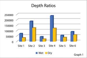
Despite error from variables as described previously, it can be argued that level-only monitors provide useful comparative information. Specifically, while the actual flow values may be inaccurate, level-only measurement can reveal differences for wet- versus dry-weather flows. Intuitively, one would expect that wet weather will produce higher levels at a given site than dry weather as illustrated in Graph 1.
Yet, there are numerous factors that can influence level changes and mask the actual flow conditions when using level-only monitors.
During a rain event, flow would appear to increase substantially based on rising level values. This appears to be the case where water levels rise concurrent with a rain event. Yet level change (depth) could be a result of a developing downstream blockage where dry-weather sediment buildup — not rain derived I&I — caused a backup.
In another example, flow appears to increase due to rain, but a downstream FOG blockage was developing at the pipe crown. Measured levels (depth) in the pipe increased due to the blockage. In both cases, these blockages and the corresponding level rise would be interpreted as RDII. If we depended on level-only measurement, this could have led to a conclusion that the area was a source of I&I — leading to expensive action, possibly rehabilitation or replacement. Instead, a good cleaning of blockages would show that these locations only contributed minor increases of I&I during rainfall.
In another instance, a large jump in level indicates that flow has significantly increased. Yet, the A/V meter data shows a much smaller increase of flow. It could be a backwater condition that just looks like an I&I issue.
False negatives
In a recent study in Washington state, level-only monitors were compared to A/V monitors, assessing their ability to identify and quantify I&I. Co-located monitors provided level data and flow data change at several locations. Hydrographs revealed a distinct pattern where the A/V monitors measured substantial flow increases, while the level-only monitors showed minor change, indicating a false negative.
In one case, two hydrographs representing depth-only measurement and flow did not correlate. Instead, the depth-only measurements showed a lower depth change, while the flow hydrograph value doubled. Therefore, if level-only monitors were used to determine I&I, the event would have been completely missed and the utility might conclude that this site had no issues.
In another example of poor level-flow correlation, the level-only monitor recorded a 1.0-inch level change in response to a 1.5-inch rainfall. Using Manning’s equation, we would calculate that this was 2.8x average flow. Yet, the A/V monitor measured 14x average flow. The level-only monitor registered a minor level change and might be ignored by the utility.
These examples illustrate how level-only monitors do not reflect actual conditions of flow. The reason is that in all cases, there was a significant increase in velocity that accounted for the corresponding increases in flow. The level-only monitors missed the velocity change altogether. Therefore, without direct velocity measurement of the A/V monitors, the flow change can be hidden from level-only monitors. Consequently, substantial I&I sources would not be detected, and these sites would be ignored for future corrective action.
Conclusions
Level-only monitors are useful for several collections system applications including SSO mitigation, optimizing cleaning schedules using real-time site feedback, reporting combined sewer overflow activation, and even backup alarming at wastewater pump stations.
Yet, level-only monitors’ attempt to measure flow and detect I&I by incorporating algorithms (any assumptive flow based on depth) for the flow calculation rely on multiple poorly controlled variables. Thus, they are a significant source of error. As presented, level-only monitors can indicate false positives from blockages and backwater and false negatives in the case of undetected velocity changes.
It’s been argued that some error is acceptable and level-only monitors can get close. But how do we define “close”? If we study 10 sites and miss I&I on 50% of them, is that close? If we only miss I&I on 20% of the segments, is that acceptable?
Rehabilitation costs can easily be in the six- to seven-figure range. That being the case, it is hard to imagine that even 20% error is acceptable when millions of capital dollars are at risk. Further, if an investment is made in the wrong sections due to error, there is no return on investment whatsoever. The low-cost and seemingly easy-to-use level-only monitors can be seductive, but accompanying this is substantial potential for error and wasted resources.
By contrast, an investment in A/V monitors that measure and compute actual flow rates will provide consistent, reliable data. In the final analysis, A/V monitors give users assurance and confidence in the results that, in turn, drive informed capital decisions and substantial returns.
Continue reading for free