Injecting chemicals to stabilize, lift, seal or compact weak soils and rocks is not new. Polyurethane grout material has been used for this purpose since the 1960s. However, the limitations of this process have often been frustrating, not only for asset owners but also installers. Historically, material injection has been limited to shallow depths of 20 feet or less, due to the technology, means and methods of application.
As the material is injected, it begins to synthesize (cure) inside the injection tube. While the synthesis rate can be accelerated or retarded by controlling the chemical temperature, that control is short-lived. The deeper or longer the injection tube, the longer time the chemical has to cure before exiting the tube. While this is happening, the diameter of the injection tube effectively shrinks in diameter as the cured material bonds to the tube wall. This limits the depth at which successful injection can occur, using the old technology. Another side effect is that the deeper it is injected, chemical being injected can lose its desired effect as it cools once leaving the tube.
This frustration is being abated by Deep Horizons Injection Grouting, a process developed by Polymer Technologies Worldwide. Their innovative method of injecting chemical grout allows the ability to inject at depths far exceeding previous limits. The following case studies describe how Polymer Technologies WW successfully injected their product to seal a leaking effluent line, with an invert depth of approximately 35 feet and an injection depth of 45 feet, at two Florida sanitary lift stations.
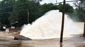
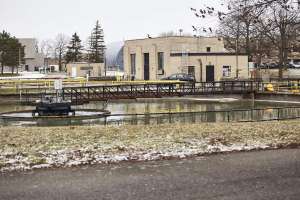
Lift Station 87 was under construction to replace existing Lift Station 7 on the wastewater collections system of the city of Sarasota, Florida. It would eventually forward about a third of the city’s wastewater flows to its wastewater treatment plant. While testing the 36-inch influent line, which crosses Hudson Bayou, city crews discovered significant groundwater intrusion through several holes, breaks and joint failures. This infiltration would cause the sanitary system to unnecessarily work harder, putting more stress on the system. That would not only waste capacity but also shorten the life of WWTP equipment over time, so it had to be eliminated.
The first repair effort was a trenchless epoxy-impregnated liner installation. While this type of largely nondisruptive repair has worked in similar circumstances, it failed to stop this water intrusion. A second effort to repair the pipe involved injection of a two-component, fast-reacting chemical grout, intended to seal the pipe from the exterior in situ. This historic method failed for reasons previously described, as the pipe is situated deeper than 20 feet.
The method considered for a third try was traditional dig-and-replace, but that would have caused extensive disruptions to surrounding infrastructure and the local population, which was why previous attempts had been trenchless. This more traditional option was estimated to add an additional $9-12 million to an already-over-budget project, along with extending completion time approximately another year for the already severely delayed project.
Highly motivated to avoid these major issues, the city took a chance on engaging the patented new DHIG process. Not only did this effort seal the pipe leaks, it also enhanced and further stabilized the foundation of the lift station structure. Best of all, because the process is trenchless and requires a small physical footprint, it not only didn’t disrupt the surrounding area, but was actually accomplished while the facility construction continued.
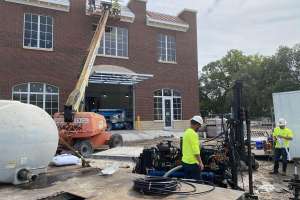
Another nearby lift station project at Symmes Road in Hillsborough County, Florida, also proved out other advantages of this new injection method. Station well inlet pipe cracks and some other damage was caused by approximately 4 inches of settling of the cover slab. Using the standard testing procedure, soils in proximity to the station — 10 feet between 18.5 and 28.5 feet below ground surface — were found to be very loose, displaying weight-of-rod conditions in which the boring tube drops under its own weight without any force applied.
The wet well for the station measures 8 feet in diameter and 30 feet in depth. To excavate and repair the station would again result in a large area of disturbance that could have possibly affected an adjacent residential community, underground utilities (electric, cable, etc.) and possibly Symmes Road itself. Again, the decision was made to take a chance on the still-new DHIG technique.
Standard ground borings demonstrated that injected material did not expand beyond the lift station property. Injecting 2,623 gallons of polymer through four injection points, with injection depths between 1 and 45 feet below grade, yielded the following results:
• Soils around the wet well were strengthened to the point where weight-of-rod conditions no longer exist.
• Soils outside the lift station footprint were shown to have insignificant change in soil stiffness. This indicated no adverse effects to surrounding properties or structures from the injection.
• The grout filled voids, stopping leaks from eroding the area around the system, and water intrusion into that system that had also caused erosion.
A post-injection analysis and report was rendered on the Symmes Road project by Integrity Drilling & Geophysical Services of Groveland, Florida. During the project covered here, testing showed good control of the material in that none of it encroached on neighboring properties. Also revealed was that soil adjacent to the grout was compacted and stabilized, despite no presence of material in those sampled soils.
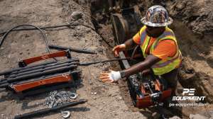
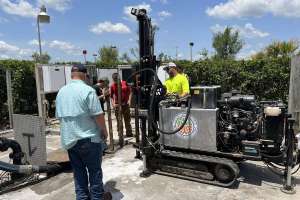
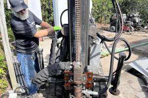
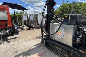
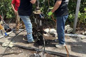
The DHIG rig is used, in part, to advance injection casing to the desired depth. The 3-inch-diameter steel casing, threaded on each end, is advanced, with new sections threaded on as needed. While skin friction is considered negligible, it takes increasing power to turn the casing as it advances more deeply. Strength and adhesive properties of the material being advanced through the casing also affect turning power.
Upon reaching the desired injection depth, the rig withdraws the casing as the polymer is injected. Care must be used to advance at an appropriate rate that avoids fouling the casing with the polymer; but not so fast that the polymer is under-injected.
To inject the polymer, a special nozzle is advanced through the casing and attached to the drilling head at the tip of the casing. This is the third use of the rig, to lower the casing head and attached chemical feed lines in a careful manner, to avoid fouling the lines or damaging the injection nozzle. Upon carefully lowering the equipment by attaching a lowering/turning bar, that bar is then rotated to lock the equipment to the head. As the casing is withdrawn, the lowering bar is removed in sections, just as the casing is removed.
The significant advantage of the DHIG process is that, theoretically, there is no limit to the depth at which the material can be successfully injected. This is due to the material being combined at the tip of the casing, which allows for full material strength to occur where it’s needed rather than inside the feed line, which is standard practice using most existing systems.
Another benefit is that the material can be injected from a lateral point to avoid interference with nearby surrounding project activity. This results in reduced time, cost and impacts to the public and the environment. For example:
• A leaking cross drain can be sealed without closing down a busy highway or interstate system.
• A sanitary lift station can remain in operation while a leaking influent line is sealed.
• A building can remain in operation while a basement wall is sealed.
• A leaking earthen dam can be sealed without lowering water levels.
• Retaining walls can be sealed at depth without excavation or injection from the face, which can further weaken the wall.
• Stabilizing embankments — bridges, railroads, roadways, canal banks, etc.
• EPA-related concerns such as underground oil, frack well, hazmat or radioactive leaks at any depth can be sealed, preventing catastrophic contamination of surrounding freshwater aquifers or ecosystems.
• Sealing abandoned wells and mine shafts while allowing for future material removal so that the well or shaft can be put back into service.
The suitability of this process and material has been successfully applied below ground without any unforeseeable limitation.
Continue reading for free