Inspection, cleaning and repairs for mainline and lateral pipes traditionally call for different equipment sets. Each task also requires its own supporting control and data acquisition systems. Rausch Electronics USA now offers a simpler way.
The company’s M-Series (M stands for modular) system can deploy a variety of specialized inspection, cleaning, testing, measuring and repair tools from a single tractor platform. Using one tractor and a variety of task-focused modules reduces hardware cost.
In addition, cross-task control systems and data management software eliminate the need to train operators on disparate systems, and free operators from having to reacclimate themselves to the controls as they move from task to task.
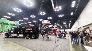
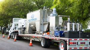
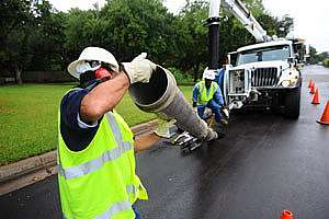
Rausch Electronics operator Jordan Newcomer and president Rudy Ellgass demonstrated the M-Series and its varied capabilities in the company facility near Chambersburg, Pa. Then, on a cold blustery December day, they deployed the system from a demonstration truck into sewer lines in Greene Township Municipal Authority in Greene Village, Pa.
Walk-around
The Rausch L135 four-wheel steerable tractor is the main platform for all combinations of M-Series modules. Each module is configured for mounting onto and being operated in concert with the tractor, which can support any of three cameras and associated luminaries, as well as other task-expanding modules.
The tractor’s boom is more than a module mounting point. Attached near the rear of the tractor, the boom positions the module in front of the tractor and is used to elevate the centerline of every module attached to it. Changing tire diameter can further elevate the boom, enabling the M-Series to work effectively in pipes from 6 to 60 inches. Stacking tires widens the tractor’s stance and adds stability for better footing in wider pipes. Stacking is achieved by adding tires on the outboard sides of already-mounted tires.
The most basic configuration is the L135 tractor with a camera attached directly to the boom. This combination is used only for mainline inspections. Whether configured for mainline or lateral inspec-tion, the first module is attached to the tractor’s boom. Each additional device is attached to the front of the last-connected module.
The tractor’s auto-steer function is controlled by an inclinometer, keeping the tractor at the pipe’s bottom dead center (BDC). If the system recognizes that the machine is tracking uphill (up the side of the pipe), it repositions the tractor at BDC. The operator can manually steer the tractor. As it moves through each traverse, information from another inclinometer senses, and the computer records, the pipe’s grade.
When the assignment includes both mainline and lateral inspection, the configuration is changed. The SKM135 Feed Module is attached to the boom. Atop the Feed Module, a series of motor-driven wheels grasp the lateral push camera’s control cable and either push the camera into or retrieve it from a lateral. The operator can use this module’s built-in nondirectional, forward-looking camera to watch the action on a display screen at the control station. The configuration can inspect laterals up to 100 feet long.
As the Feed Module manages the camera’s forward/backward movement, it relies on the PM135 Positioning Module to manage the direction toward which the camera will be pushed. This module is mounted on the front end of the Feed Module.
The Positioning Module’s rota-tion and pan range enable introduction of a KS60CL lateral camera into a lateral at any point on the mainline pipe’s circumference. A rigid steering pin resembling a cat’s whisker can be attached to the camera to help the operator introduce the lateral camera into the lateral opening. The coordinated action of the Feed and Positioning modules guides and pushes the camera.
Three camera modules are available, and the operator selects the one that best suits the task. All camera modules have pan-and-tilt capability, software-enabled self-righting imagery, and integral LED illumination. They all use the camlock and integrated spring-loaded electrical contact system. All rely on a dedicated power/control/data cable to send the imagery to the computer in the support vehicle. A radio sonde for locating purposes and auxiliary light attachments are available as options.
The KS135 camera is primarily for inspections in mainlines from 6 to 60 inches. The KS135 Scan camera inspects mainlines up to 48 inches. This camera has a pair of embedded laser lights which, with the proper software, enable instant analysis of pipe deformity (out of round). The lasers are also used to measure defects, all captured on the onboard computer. The KS135 and the KS135 Scan cameras have 10X optical and 12X digital zoom capability.
The KS60CL camera, which easily fits in a 4-inch pipe, is primarily for lateral inspection but can do double duty as a mainline camera.
Additional modules add to the M-Series’ versatility. For cases where debris is encountered in a pipe, the Feed Module can be converted to transport and operate the TSS150 kit, which allows attachment of a pressurized jetter in the position usually occupied by the KS60CL camera. The jetter and its supply hose must be supported either by a separate truck or by equipment provided by a third party. The same Rausch control module is used to introduce the jetting module into a lateral. The operator monitors the action through the forward-looking camera on the Positioning Module.
A variety of modules are available for pressure testing pipe segments from 6 to 24 inches in diameter at individual joints, or for segments up to 15 feet long. Modules also can enable spot repairs for pipes ranging from 6 to 32 inches, although that process requires one or more of the components used for inspection and a separate source of compressed air.
Operation
The M-Series components were supported by a demonstration truck equipped with a climate-controlled operator’s cabin that housed a rough-duty protected computer with equipment control and data recording systems and POSM pipe survey software (RS Technical Services).
The computer had an Intel Core i5 CPU operating at 3.33 GHz. Three GB of RAM were installed along with a 160 GB hard drive. The console and a computer monitor focused the operator’s attention in a compact ergonomically friendly workspace.
Deployment and support equipment were housed in an open-air section where a modest workbench, tool rack and storage spaces were installed. An onboard Cummins Onan 5 kW generator, the smallest capacity Rausch will install, powered all onboard electrical equipment.
The L135 tractor was stored in a slide-out tray directly under the deployed crane-like arm and winch system that introduced and retrieved the modular system. Additional storage spaces held a variety of tire sets, various other modules, and supplies and tools.
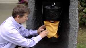
The demonstration began on the workbench in the rear of the company’s demonstration van in the Rausch facility. There, Newcomer configured various modules to conduct pre-deployment inspections. He also checked the pressure level of the nitrogen used to prevent liquid intrusion into the tractor and every module.
As Newcomer changed from module to module, each change illustrated the quick-connect and quick-release capabilities of the modular design. Each component became a semipermanent addition to the component to which it was mounted.
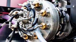
Physical connections were achieved by a watertight, double camlock fitting. Within the body of the fitting were a series of spring-loaded electrical contactors that transfer information, control commands, video signals or energy to each component. Ellgass explained that the spring-loaded contactors maintain circuit continuity while eliminating the potential for failure inherent in friction (spade-and-post or male-female pin) contacts.
When Newcomer was satisfied that each component was ready for use, he assembled the tractor, Feed and Positioning modules and a KS60CL camera into a dual-purpose unit, which he stowed in and secured to its transport rack. The demonstration then moved to the field.
There, after traffic control cones were deployed, Newcomer put the configured system through a final lights check and deployed it into an 8-inch sewer. Inspection proceeded up the line, gathering general data and a continuous video file. Because the line was less than two years old, no defects were observed. At various points, Newcomer stopped the tractor and demonstrated its pan-and-tilt capabilities.
On the return, which was simplified and accelerated by the auto-matic synchronization of cable retrieval and the tractor’s reverse movement, Newcomer inspected laterals as the tractor reached them. Using the control systems at the workstation, Newcomer positioned the tractor, then switched to active control of the Positioning Module and Feed Unit. By turning the camera toward the lateral and combining rotation with incremental deployment moves, he easily introduced the lateral camera to pipe.
As the camera moved toward the house, the POSM data and image-capture systems created and then preserved a record of the inspection. Retrieving the camera was uneventful. When the tractor returned to its neutral (forward-looking) position, retrieval continued until the next lateral connection. At the end of the traverse, Newcomer retrieved the tractor using a specialized hook that slipped under two docking pins on the tractor.
All that remained was tractor cleanup and stowing. If Newcomer had encountered defects, he would have entered their location, type and severity into the computer’s data-capture system, coordinating the data and imagery with their precise location.
Observer comments
The dual-purpose, quick connecting camlock lived up to its name. It took minimal handwork to configure and connect modules, using only T-handled Allen wrenches.
The
operator workstation was spartan, functional and comfortable, despite the windy 25-degree day. A bulkhead window gave the operator direct visual observation of the work area. A down-looking camera over the manhole enabled additional surveillance of the work area.
Every M-Series module is available in an EX version, certified for use in potentially explosive environments found in pipe systems like those in a leachate collection system at a landfill. The entire inspection process was paperless.
Manufacturer comments
“Buried conveyance systems that carry sewage or potable water, or exhibit hazardous environments, are all settings the M-Series is suited to inspect and maintain,” said Ellgass.
He noted that modularity brings diversity and adaptability to the equipment and reduces operator training, as the software and control systems are the same.
“Every core component is built in Germany, and each is maintained and serviced in our location in Chambersburg, Pa.,” Ellgass added. “Operator training is provided at that location, or at the buyers’ locations, using the equipment they have purchased.”
Continue reading for free