Purpose
This paper's purpose is to independently assess the requirements for accuracy testing compliance of water meter test bench systems used to provide modern utility testing solutions for ANSI/AWWA C715 electromagnetic and ultrasonic meters. It is not intended to compare different water meters or their manufacturers. This evaluation focuses on the requirements of water meter testing equipment necessary to comply with the ANSI/AWWA C715 standard.
The analysis draws on publicly available information, physical inspections of the test bench systems, written input from vendors, and direct confirmations from the manufacturers regarding C715 compliance. Furthermore, this paper is not meant to endorse any specific manufacturer. Instead, it provides a detailed technical examination of the requirements for meter test bench systems necessary to comply with the ANSI/AWWA C715 standard.
Significance of Compliance
Compliance with ANSI/AWWA C715 is crucial for ensuring the accuracy and reliability of water meter test bench systems. For utilities, adherence to these standards means that their water meters are tested under conditions that closely mimic real-world usage, thereby guaranteeing precise measurement and billing. This compliance also enhances consumer confidence in the utility’s metering and billing processes, minimizes revenue loss due to inaccurate meters, and supports regulatory adherence. Moreover, it helps utilities avoid potential legal issues and ensures the efficient allocation of resources by reducing the need for frequent retesting and meter replacement.
Compliance Criteria
The requirements, as outlined in the American Water Works Association documents, ANSI/AWWA C715 on Cold-Water Meters—Electromagnetic and Ultrasonic Type, for Revenue Applications and the M6 Manual Water Meters – Selection, Installation, Testing and Maintenance (“M6 Manual”) provide the foundation for the primary requirements.
- Straight pipe / full bore throughout test system, including no cavities that could cause flow disturbance (i.e., no bleeder valves)
- No constraints or “pinch points" to restrict flow
- Evidence that the test bench system undergoes annual maintenance and system calibration
The AWWA C715 Standard, Section A.3.3, specifies adherence to the quality of the meter testing device (also known as a test bench or test stand).
Test quantities shall match manufacturer recommendations to ensure that adequate sample intervals are included in the test process.
Test equipment should provide full-bore diameter fittings for the meter size being tested and a constant flow stream that is free from disturbances. When two or more meters are being tested simultaneously in a single line, some meter designs will require at least five diameters of straight pipe between the outlet of one meter and the inlet of the next meter in line. This straight pipe will minimize the errors associated with flow profile disturbances created by meter internal flow geometries.
If the purchaser does not have suitable means for testing, the manufacturer should be requested to provide a certificate showing that each meter has been tested for accuracy of registration and that it complies with the accuracy and capacity requirements of ANSI/AWWA C715 standards.
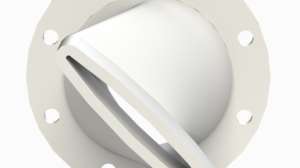
The “full-bore” criteria are a key measure in determining the accuracy of the C715 meter. Full-bore means to operate at the fullest extent with minimal intrusion. The “full bore” or “straight pipe methodology” ensures that the test bench does not introduce disturbance (formerly known as turbulence) into the testing system. This disturbance can potentially affect the meter performance and may result in inaccurate test results. These disturbances may cause the meter (or meters) to fail the accuracy test, producing concerns related to, but not limited to, vendor selection, revenue loss from under-performing meters, workforce loss due to retesting of the failed meters, and unnecessary replacement of accurate meters.
The straight pipe methodology is achieved by providing meter settings or adapters that do not leave any gaps, spaces, or areas that would allow water to sit, swirl, or form air pockets.
Previous meter technologies allowed for the bleeder valve to be opened at each test bench position, enabling the operator to set the dial on the register to an 'acceptable' starting point, ensuring an accurate starting point in the meter read and subsequent test. However, current technologies with digital displays on meter registers render this function obsolete. Water may collect, sit, or swirl at the point of entry to the valve, causing disturbances that do not meet the requirements of straight pipe or full-bore compliance. Additionally, bleeder valves are used to release pressure at each station, minimizing water jetting from the meter positions on the test bench. The bleeder valve can be placed at the end of the row on the test bench, but water may still collect, sit or swirl, leading to noncompliance. Similarly, the placement of saddles and adapters to fit various meter sizes often requires an adapter on both sides of the saddle, creating a gap that causes disturbances and fails to meet straight pipe or full-bore compliance.
For more about ANSI/AWWA background, additional information on meter testing, testing requirements for the AWWA C715, and sources, download the full white paper.
Download White Paper