Pipe inspectors often spend many hours with a camera crawler stationary while they pan, tilt and rotate a camera to create a videotape record. Real-time fault analysis may require more stationary time.
The DigiSewer 180° Inspection System from Envirosight LLC of Randolph, N.J., captures digital images that can later be manipulated as if the crawler was stopped and the camera itself was manipulated in the traditional manner.
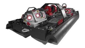
DigiSewer digital sidewall scanning is designed for the company’s ROVVER inspection crawlers. Its purpose is to enhance the speed and detail at which pipeline inspection is performed. When scanning is complete, municipal personnel can analyze the scans using a freeware viewer, zooming in on areas of interest and making measurements and annotations directly on the scan.
Envirosight representatives demonstrated the technology on Sept. 15 in a 30-inch storm sewer and a 6-inch sanitary sewer in the Township of Upper St. Clair in suburban Pittsburgh, Pa. Marketing manager Jake Wells and sales manager Jason Kelley (from the company’s Pittsburgh office) gave the demonstration. In routine service, the unit is intended for one-person operation.
Walk-around
The DigiSewer system was installed in a 2007 Dodge Sprinter van the company has set up for demonstrations. The van is built on a FreightLiner chassis with a Mercedes 5.5-liter diesel engine.
The climate-controlled workstation provides space for the inspection operator and two or three observers. The workspace has access to the rear equipment bay through a bifold door. A window in the partition lets the operator directly observe what is going on behind the vehicle.
A downward-looking video camera displays the manhole being accessed on a dedicated screen in the operator’s work area. There are two workstation monitors. One presents camera-captured images as the crawler moves through the pipe at top speed from 56 feet per minute (ROVVER Model 100) to 70 feet per minute (Model 225). The other monitor is used for computer interface operations.
The equipment bay positions a crawler storage drawer and crawler- related communications and tethering cables directly within reach. The storage drawer has a custom-fitted cradle to prevent crawler creep while the van is in transit. Built-in racks and brackets on both doors secure a variety of tools for travel, yet allow for easy one-hand removal and replacement.
A washdown hose on a retracting reel can be reached without entering the bay. A 15-gallon onboard water tank provides washdown capacity for a full day’s field work.
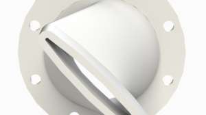
The DigiSewer camera with its attached super-white LED illumination is easily inserted in the camera mount on the crawler and is connected using standard Envirosight connections. The extra-wide-angle lens is interchangeable; no adapters are needed. The camera has automatic white balance, autofocus and light sensitivity greater than 1 lux.
All crawler movements are controlled from either the operator’s workstation or at the back of the van. Each control site has two joysticks, a variety of push-buttons and rotating knobs to control specific functions. At the back of the van the controls are housed in a rough-service box at the end of an 8-foot-long flexible cable. This allows direct observation and control of the crawler as it is deployed into a manhole and maneuvered for entry into the pipe.
Power is supplied for the crawler, computer, cable winches and all other ancillaries by a 3.5-kW Onan power inverter/battery system. At night, the inverter is plugged into a 110-volt outlet at the garage, and the 12-volt or 24-volt DC battery pack is charged. At the work site, the battery current is converted to 110 volts.
WinCan survey software was loaded into the onboard computer, configured with an Intel Core 2 Duo e8400 processor running at 3 Ghz. The software continuously interacts with the DigiSewer software.
Operation
After insertion of the crawler in the traditional manner, the camera and software demonstration began. At the first pipe joint, the operator calibrated the software for the pipe diameter using joystick and keyboard control.
A crosshair is placed in the center of the bore, and concentric colored circles are superimposed on the image to correspond with the pipe walls. Calibration ensures that the software recognizes the pipe’s center and perimeter. Subsequent insertions into same-sized pipe using the same crawler do not require recalibration. Calibrations for different crawlers and pipe diameters can be stored in the software and retrieved for reuse. Calibration took about one minute.
The image from the camera was displayed on-screen and seen through the WinCan software’s viewing panes. The video signal was continuously saved to the computer’s hard drive and can be transferred to a DVD or external drive. If there is sufficient network capacity, the file can be transferred or e-mailed via a hard-wired or wireless network.
The smooth, good-condition pipe enabled the operator to demonstrate speeds close to the specified maximum of 45 feet per minute using the Model 145 ROVVER crawler. When the traverse was completed and before the crawler was signaled to back up, the operator scanned the thumbnails, doing a quick QA/QC check.
During the backup movement, the rearward-facing camera enabled the operator to monitor progress. A tension sensor on the cable reel ensures that cable retrieval and crawler speed are coordinated. The crawler never overran the cable.
The entire traverse for a 400-foot pipe segment took less than 15 minutes. More time was spent setting up, deploying, retrieving and cleaning the crawler than was needed for the data capture.
With data capture complete, the demonstration turned to data evaluation. The WinCan ScanExplorer software enables selection of any of four views, all presented simultaneously in four panes on-screen. Actions taken or annotations made in the active pane are also shown in the other three panes.
The frontal or straight-ahead view is the one the operator uses most frequently. This captured image is what the software slices, flattens and otherwise manipulates to create the three other views. The frontal view is the only view that does not benefit from the zoom magnification feature.
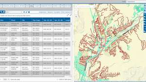
The thumbnail view showed a rectangular strip view of the entire traverse. On screen, this resembled a series of geologic core samples. To achieve this view, the software digitizes the donut-shaped sections from successive video frames. Each frame section was cut at the 12 o’clock position and straightened into a vertical strip.
The sections were then stitched together side-by-side to create the scan image. The pipe’s bottom dead center was seen at the center of this strip scan. The top of the strip is the 11:59:59 position; the bottom is the 12:00:01 position. For viewing on-screen, the strip was wrapped from one line to the next like text on a page flowing from left to right and top to bottom. Fitting within the enclosing frame of the thumbnail pane, the traverse began at the top left and ended at the bottom right.
The side view displays a rectangular portion of the thumbnail. Although called a side view, this view can present any portion of the thumbnail regardless of its position on the pipe wall.
The 3-D view enables traditional pan-and-tilt observations.
The demonstrators showed how virtual digital measuring tools that determine the length or area of defects can be overlaid on any of the three views. Polygons, circles and rectangles were drawn, and the software calculated the contained area and recorded it.
Linear faults were measured by a series of connected lines, and their areas were also calculated and stored. Color-coding of area and linear notations can be retrieved and also removed from the stored image if it is necessary to revisit an unannotated view. The total area of faults for each traverse is calculated and stored.
When used in tandem, the camera and two software applications enable scanning and data capture at up to 5,000 linear feet in an eight-hour workday, according to the Envirosight representatives. Data evaluation can be completed at roughly double that pace using either the onboard computer or on a computer at a remote location.
In this demonstration, data evaluation began in the thumbnail view pane, where faults were quickly identified. A mouse-click took the technician to the side-view pane, where the measuring shapes and lines were laid over the image. A few more mouse clicks and the square footage of the needed repairs was calculated and stored. This information will be exported for use in estimating needed manpower, materials, time and equipment for repair.
Observer comments
The thumbnail view is one of three capabilities that enable significant time savings. With the entire traverse displayed on a single monitor, faults stand out. A few mouse clicks brings the technician a magnified view of suspect areas.
Using the measuring tools, the user can calculate the volume of repair materials needed. In turn, this information enables selection of the best repair techniques. The precise location of each fault is also determined.
This collaboration of traditional crawler, extra-wide-angle lens and dedicated software enables continuous forward moving, high-speed, single-pass data capture. Although not as fast, backing the crawler to the insertion point is made easier by a rear-facing camera that the operator can watch during backing movements.
The inspection system appears versatile. By adding the extra-wide-angle lens and software to an existing ROVVER crawler, users can quickly upgrade to sidescan capability. If the purchase represents a user’s first entry into crawler-based inspection, the purchase of a different camera head or lens adds conventional CCTV capability.
Manufacturer comments
The DigiSewer system with the crawler and a support vehicle can be purchased as a complete unit. The entire system — crawler, camera, computer and control station, and self-contained power supply — also can be packaged in a transportable 4-foot metal cube, which is usually fitted with forklift receiver slots and may be fitted with lifting loops. This enables pickup truck or ATV deployment to remote locations.
“Current crawler operators quickly adjust to the straight-ahead operation, and data evaluators will be able to quickly master the measuring tools and annotation processes,” says Wells.
Data evaluation is done in an office and requires far less time than evaluation performed on videotape, the Envirosight representatives say. After problem areas are identified, the digital image technology lets the reviewer zoom in on, measure and annotate faults. “When fewer people do data evaluation, the resulting reports are more consistent,” Wells observes.
Continue reading for free