Accurate assessment of the condition of underground pipes is essential for efficient planning of maintenance, rehabilitation or replacement.
Imagine having a 3D model of those pipes — one that can be rotated, panned, zoomed, and measured on a computer screen. That’s what users get with the CoolVision 3D laser profiling system from Aries Industries Inc. It does so with nearly the same workflow as conventional CCTV inspection systems.
The laser profiler complements CCTV cameras, which are still needed for the visual record. The fully interactive onscreen 3D model allows easy measurement of critical parameters such as distance, inclination and ovality (deformation), while the synchronized video shows defects such as cracks, bad joints, roots, and interior scaling.
By projecting a circle of laser light on the section of pipe ahead of the camera, recording the image of that projection, and then analyzing the image with sophisticated 3D processing software, the system creates a highly accurate 3D model of the pipe interior. Later, at the user interface, the 3D model can be displayed concurrently with visual data from the CCTV camera and graphic data on the parameters of interest.
Joe Vannieuwenhoven (known as Joe Vann), product manager for Aries, and Jerry Botts, president and CEO of Botts Consulting Group, exclusive marketing representative for CoolVision, demonstrated the technology April 16 in Gilbert, Ariz. The test included a 500-foot data run in a 24-inch PVC pipe 25 feet below a city street.
Walk-around
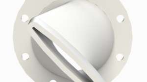
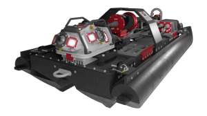
The CoolVision laser profiler is a self-contained unit designed to be towed behind a standard non-steerable camera tractor or pulled by cable. The unit is not self-propelled, but couples easily to any tractor using the included hardware.
Coupling is accomplished with a rigid hitch that allows up-and-down motion as needed for changes in inclination, but resists side-to-side deflection. The minimum pipe size for profiling is 8 inches; the maximum is 48 inches. The computer software can adapt to circular, elliptical, or arched pipes, but not to square pipes.
Other accessories modify the laser profiler for larger-diameter pipes. These include hub extenders for better centering, and extender brackets to better position the laser and camera modules. In larger pipes, the image of the projected circle of laser light would otherwise be out of frame for the camera. It is the shape of the projected circle, along with data from an onboard 2-axis inclinometer, that provides the information needed to build the 3D model.
In a pipe carrying water, the laser light refracts at the air-water interface, stretching the projected circle on one side and skewing the data. The software that creates the 3D model recognizes this, and ignores that skewed data. In its place is simply a gap in the visual model that makes it look like the bottom section of the pipe is missing. The modeling software only needs 55 percent of the complete circle to extrapolate the data and create a full 3D model.
Projecting a circle of laser light gives the system its inherent accuracy. Some laser profiling systems use points or bars of light, providing less geometric data to describe the pipe in three dimensions. By recording 2,000 points of data at 30 frames per second, the system attains 0.25 percent accuracy and 99.9 percent repeatability, according to Aries.
Positional data is obtained via transducers in the wheels. Looking much like 48-tooth sprocket gears, these heavy, stainless steel wheels turn without slipping and register distance in direct proportion to their rotation. Positional accuracy is maintained at speeds up to 50 feet per minute, well in excess of industry standards.
Data is transferred to a computer in the camera van on a cable that contains 12 conductors, including a coaxial cable. There it is encoded into a format readable by the modeling software. Next, the data is transferred via DVD or FTP to the C-Tec Data Analysis Center in Montreal, Quebec, where proprietary software creates the 3D model. Results are returned to the client via a written report and DVD within 48 hours.
As an example of the volume of data generated, eight hours of measurements will fit on one DVD (4.7 GB), or require about three hours of broadband uplink time. Video data is encoded in MPEG-2 format and includes a multiplexed data stream recording distance, inclination, light levels, deformation, internal humidity (of the profiler), and a data parity check.
Operation
A crew from the City of Gilbert arrived early with a vacuum truck, and had the manhole opened and cleaned by 9 a.m. At 10 a.m., Vann and Botts began their demonstration with an overview of the product, followed by questions and answers for the city crew. This included a look inside the camera van, where the operator console and computer were located.
By 10:30 a.m., Vann and Botts were ready. After hitching the laser profiler to a camera tractor, they lowered the combined 75-pound unit 25 feet down the manhole and into the 24-inch metal pipe. An onboard winch and manhole-mounted cable roller made the process easier. Once the equipment was inside the pipe, they used the tractor motor to level and position the laser profiler at the end of the pipe and calibrated the starting point.
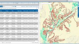
At the console, Vann started the data run by simply switching on the recording software and activating the tractor. Moving at 40 to 50 feet per minute, the laser profiler covered the 500 feet to the next manhole in less than 15 minutes, all the while streaming real-time images and data to the monitor. There, the Nexus Loader front-end software displayed a tri-window view showing the projected circle of laser light, the CCTV video feed, and a graph of all measured parameters.
Even without the 3D model, Vann’s trained eye could see from the shape of the projected circle of laser light that this pipe was sagged in some sections and deformed in others. With the 3D model, these defects would be immediately obvious.
To demonstrate another capability of the equipment as set up, Vann stopped the unit in mid-pipe, focused the camera on the interior surface, and used a MilliM video micrometer, a tool used to accurately measure cracks and joint gaps in pipelines. By projecting a set of parallel and perpendicular lines, the operator can tell when the camera’s line of sight is perpendicular to the pipe surface, a necessary condition to avoid parallax errors during measurements.
Thus calibrated, Vann pointed out the now-onscreen image scale and used the cursor to draw a line between two points on the pipe surface. The properly scaled length of this line was immediately displayed and recorded.
After retrieving and stowing the laser profiler and camera tractor, Vann and Botts ran another short question-and-answer session to explain what would normally happen next. As this was only a demonstration, the data would not be forwarded to C-Tec. Instead, Vann loaded a sample DVD from another job to show immediately what the 3D model would look like.
With the 3D model onscreen, Vann showed how he could scroll back and forth along the pipe to an area of interest. The CCTV camera view and a graph of pipe ovality (deformation) were simultaneously displayed and synchronized with the cursor position.
Then he zoomed in on a color-keyed section of the model that indicated high deformation, and rotated the image for the best view. It was clear that the deformation was not uniform, as it would be under normal soil loading conditions, and instead likely was due to premature failure of that section of pipe.
Observer comments
Mechanically, the laser profiler is a simple system that can interface easily with any camera tractor. Lowering and deploying a “train” of two connected units (camera tractor plus laser profiler) is obviously more difficult than deploying a single camera tractor, which weighs about half as much. Still, deployment proceeded with no problems, even in a 25-foot-deep manhole.
The results, though simulated in this demo, were impressive. Vann manipulated the 3D onscreen model, rotating and zooming to point out features like sag and deformation. Simultane-ously onscreen were the visual record from the standard CCTV camera, and the graphic display of measured parameters, all keyed to position and fully scrollable up and down the pipe.
With only a single pass required for data acquisition, no additional time beyond that required for a standard CCTV inspection was needed. Given how much additional information is acquired, and the accuracy of that information, this system appears to increase data return significantly for the time invested in field inspections.
Manufacturer comments
Vann notes that the laser profiler is designed to minimize operator setup and to eliminate post-inspection data analysis in the field. “The operator completes the laser profiler and CCTV inspection at virtually the same productivity level,” he says. “There is no need to field calibrate, because the system automatically does this every second as it measures the actual inside pipe dimension with every profile.” The equipment is annually certified by an accredited independent testing agency.
For end user convenience, the data is delivered first in raw format as part of the laser video to a third-party company, where software automatically reads and analyzes the information before final verification by a specialized technician. The inspection deliverables include a PDF report of the Deformation (Ovality) Graph, Flat Analysis Graph, and picture index. The Nexus software is provided on DVD and includes both videos synchronized, the 3D pipe view for ovality, the deformation graph, and other pertinent information.
Continue reading for free