Pump selection and physical design (parts 1 and 2 of this series) represent the greatest portion of the pump station design task. However, proper function requires a variety of ancillary systems. These may not be the most expensive parts of the project, but they are often critical for efficiency and operator satisfaction.
Variable or fixed speed
In many installations, process considerations influence the operating mode of the pumps. For example, variable-speed pumping at the headworks of a treatment plant can minimize slug loading to the process. However, the most common justification for variable-speed pumping is energy cost reduction.
Variable-speed pump performance is based on the affinity laws:
- q1, q2 = initial and new flow rate, gpm
- n1, n2 = initial and new speed, rpm
- h1, h2 = initial and new head, feet or psi
- P1, P2 = initial and new power, hp or kW
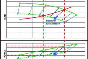
The affinity laws should be applied to the pump characteristic curves and used to create curves at the new speed. Superimposing the system curve will allow the new operating point to be determined. A common error is applying the affinity laws directly to a known operating point without consideration of the system curve. This can result in very inaccurate values. The amount of error depends on the nature of the two curves (Figure 1).
Small stations may be billed on energy consumption alone. Larger stations may be billed at different rates for energy based on the time of day. Even larger stations will also be billed for peak demand — the highest power consumption during a month.
If the system curve is flat — primarily static head with little friction — and the station is billed for energy consumption only, then using variable-speed pumping results in little cost reduction. On the other hand, systems with high-friction head that are billed for demand charges will save money with variable-speed pumping because of two phenomena. First, a lower flow rate will reduce friction, which will in turn reduce pump head and power, and total pumping energy. Second, the reduction in pump power from both lower flow rate and lower head will decrease peak demand.
Control considerations
Control for many pump stations consists of float switches and across-the-line motor starters. The lead pump is started when the high-level switch trips and continues pumping until the low-level switch trips. When multiple pumps are to be operated simultaneously, additional float switches are used to start them when the wet well level rises.
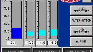
For wastewater pump stations, the pumps are usually operated based on maintaining a constant wet well level. This matches pump flow rate to influent flow rate. As the level of the wet well increases, the pump speed rises to maintain the level at the setpoint.
A variety of devices can measure level. Submersible pressure transducers, designed to prevent fouling, are inexpensive and reliable. Some owners prefer non-contact devices such as ultrasonic level transmitters. Still others rely on bubbler tubes, with a continuous flow of air minimizing fouling.
Motor controls
Motor control is common to all pump stations. All but the smallest pump motors utilize three-phase power. Three-phase motors are more efficient, more reliable and lower in cost.
Voltages range from 208 volts to 4,160 volts, but 480 volts is the most common. The means used for starting and protecting motors varies with the pump control method and power.
Small stations use across-the-line starters with built-in overload protection. At higher horsepower (typically dictated by the electric utility), reduced-voltage starters are used to limit motor inrush current. State-of-the-art reduced-voltage soft starters use solid-state devices instead of mechanical contacts. In addition to overcurrent protection, most soft starters include low-voltage and phase imbalance protection. RVSS life is extended if contactors are used to bypass the solid-state components once full speed is achieved.
Variable-frequency drives are usually the method of choice for variable-speed pump control, although magnetic couplings of various designs are also available for special applications.
VFDs include motor protection and eliminate the need for starters. Bypass contactors may be justified in remote locations to allow operation if the VFDs fail.
Enclosure selection for motor controls and instrumentation can have a significant impact on cost and reliability. Small starters and VFDs are usually wall-mounted. Large stations generally install motor control centers to simplify wiring and reduce space requirements.
Moisture and corrosive or explosive gases are produced by wet wells, and appropriate precautions must be taken against them. Locating enclosures in ventilated locations is good practice. Small stations commonly mount NEMA 3R weatherproof enclosures outdoors. Larger stations should install the controls in a ventilated space separated from the wet well and directly accessible from outside.
There is a temptation to specify washdown-rated NEMA 4X stainless steel or explosion-proof enclosures for everything electrical in a pump station. These enclosures have advantages in some applications, but they should only be used when needed. This is particularly true for VFD enclosures, where heat dissipation issues are a problem for sealed enclosures.
Because of methane occurrence, intrinsically safe instrumentation should be installed in wet wells or intrinsic safety barriers should be used in dry well mounted panels. The importance of entry permits and proper safety precautions for wet wells and confined spaces cannot be overemphasized. When in doubt, a qualified expert should be consulted to identify proper procedures.
Generators
Because pump stations need to operate regardless of weather, standby power is a necessity. In some cases it is sufficient to have power fed from two independent sources. The designer must ensure that there is not a single point of failure, such as a common utility pole, that could interrupt both sources.
For many pump stations, standby generators are used for emergency power. These may be portable units towed to the station for quick connection or permanently installed.
The need for electrical safety cannot be stressed enough. Proper interlocks must be installed to prevent “back feeding” power from the generator into the grid. Installations should be reviewed with the electric utility. Proper maintenance and periodic testing is mandatory.
Generator sizing, measured in kVA, involves more than adding motor nameplate power. Inrush current when starting motors usually dictates the generator size, especially when pumps are started across the line. VFDs also influence generator selection by causing harmonics and voltage distortion that increase the required generator rating. Altitude, ambient temperature and miscellaneous loads such as lighting also need to be addressed.
Screening and scum handling
Wastewater and stormwater pumping stations must cope with solids entering the conveyance system. These range from large objects like logs, to grit and similar non-putrescible materials. Solids can accumulate in the wet wells, cause odors and damage pumps.
Some utilities prefer to remove as many solids as possible at the pump station and use fine screens before the wet well. Others use trash racks to only remove debris that would damage the pumps, but allow smaller objects to pass through to the treatment plant.
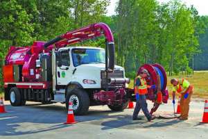
Some stations try to minimize scum accumulations by adding chemicals or special bacterial cultures. Others periodically pump down and clean the wet well to remove accumulated scum deposits.
Regardless of philosophy, periodic cleaning of wet wells is necessary. Access for maintenance and cleaning must be provided, with provisions for continuing operation during service.
Ventilation and odor control
Proper ventilation is necessary to prevent deterioration of equipment and allow safe access by staff. In most jurisdictions, codes establish minimum ventilation requirements.
Dry wells may be continuously ventilated to minimize moisture and gas buildup. Wet wells are commonly ventilated intermittently (only when occupied), but may also be ventilated continuously. Ventilation is typically expressed as air changes per hour, and fan flow may be calculated based on the volume of the space ventilated:
- Q = fan airflow rate, cfm (cubic feet per minute)
- ACH = air changes per hour:
- Wet wells = 12 continuous, 60 intermittent typical
- Dry wells = 6 continuous, 30 intermittent typical
- V = volume of space ventilated, cubic feet
Because pump stations include confined spaces, all necessary safety precautions should be rigorously observed. Monitors for hazardous gases, either portable or fixed, should be provided.
Odors in wastewater applications are inevitable. Some odor control measures are simple and inexpensive. Designing the wet well to reduce turbulence minimizes odor release. A tall exhaust stack can reduce the effect of odors by releasing them above the level of nearby structures.
More elaborate methods are often employed to reduce odors. Chemicals may be fed into sewers or wet wells to minimize formation of
noxious gases. Scrubbers on exhaust ducts may utilize chemical sprays to neutralize odors. Filter beds to remove odors may use activated carbon, chemical pellets, sludge or various natural media. All of these methods may be effective, but proper maintenance is essential for long-term performance.
Pump station design can be a complex topic, and volumes have been written on the topic. This series of articles is far from exhaustive. The principal design considerations identified should enable the owner to work with design professionals and suppliers to develop systems that meet their needs and provide long-term value.
About the Author
Thomas Jenkins is a professional engineer and the owner of JenTech Inc. in Milwaukee, Wisconsin.
Continue reading for free